|
|
| |
|
|
|
|
|
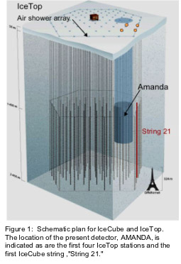
| A schematic diagram of the IceCube Neutrino Observatory when finished is shown in Fig. 1. The strings, each of which will have 60 sensors, or Digital Optical Modules (DOMs), are arranged in a hexagonal pattern. The size of AMANDA, which was completed in 2000, is also indicated. The red line denotes the first string IceCube string, deployed in January of 2005. During the present season, a year later, eight more strings were deployed in the same vicinity as String 21. |
|
| |
|
|
|
|
| The goal of the IceCube design is to deliver high quality data that contain the maximum amount of useful information from each sensor. The most interesting events are likely to occur very infrequently and their detection and unambiguous reconstruction may require all the information a photomultiplier tube in a DOM can deliver. The electronics, once deployed in the ice, are forever physically inaccessible - therefore they must be highly reliable. |
|
|
|
|
|
|
| |
 |
|
| |
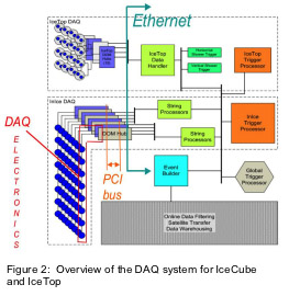
A schematic diagram of the Data Acquisition System (DAQ) is presented in Fig. 2. The DAQ begins with the individual DOMs on each string in the ice and in the IceTop tanks on the surface. The information flows in digital format along cables to the surface where it arrives in the DOM hub. Further processing there converts this information into a form suitable for transmission by the Ethernet protocol to subsequent processors that sort through all the signals to find the ones that correspond to interesting events. |
|
|
|
LBNL is involved in the design and construction of the main piece of electronics, called the "mainboard," which is located in the DOM. The mainboard communicates with another piece of electronics, the "DOR" card, which is located on the surface inside the DOM hub, over an electrical cable up to three km long. While LBNL has overall responsibility for the entire DAQ system as described in Fig. 2,
|
|
| the work involves other institutions in the collaboration as well, and the coordination of this effort is itself a significant task.
The DAQ components and associated effort are conveniently divided into Hardware and Software. The custom-built electronics are all located inside the red box in Fig. 2. It is here that the signals are processed in real time and nanoseconds are important. Once the information emerges from the hub, the subsequent hardware consists of commercially available computers and network switches. However, as is also the case the real-time portion of the system, the Software must be custom-developed and written for IceCube. All of the software modules must function together in order for the detector to operate and take data. The software system that accomplishes this is called "Experiment Control." |
|
| |
|
|
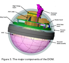
The DOM is effectively the foundation of the DAQ system, and is described in Fig. 3. It includes the photomultiplier tube, which converts single photos of light into an electrical pulse, and the mainboard electronics that processes these pulses. All these components are contained within a glass sphere that can resist the approximately 250 bar of water pressure at the bottom of the hole (before the water freezes) and the crushing pressure of the ice when the water freezes some days after the DOM was deployed. The highest quality data are obtained by |
|
 |
|
recording the PMT waveform locally, which enables digital transmission to the surface. Time stamping the digitized waveform (so that we know when the photon of light arrived) requires that there be a local clock, i.e. a local oscillator, which is calibrated against a master oscillator on the surface. The master oscillator is itself calibrated against a GPS clock, which provides an accurate universal time.
These components and systems to which we are contributing are described in more detail in the following sections. In order to verify that the detector design is working properly and delivering data according to expectation, a series of tests must be performed to verify performance. Our effort in verification, monitoring and calibrations is also described in the following web pages.
A more complete technical description of the DAQ electronics and its performance as shown by String 21 can be downloaded here (PDF).
|
|
|
|
|
|
|
|
|
|
|